Maxpower Construction Machinery Manufacturer




A contractor needs to place a concrete chamber beside a trench. The excavator is already on site, and the chamber's weight is known. It is tempting to compare that weight with a single figure on a machine brochure and approve the lift. Yet the chamber must be picked up, moved through a defined path, and lowered at a particular distance from the excavator. Its lifting gear adds weight, and the machine may be facing a different direction when the load reaches its destination.
Excavator lifting capacity is not a single number that applies to every position. A manufacturer load chart relates rated capacity to a specified lifting-point radius, height, direction, and machine configuration. Understanding that relationship helps buyers ask useful questions before deciding whether an excavator is appropriate for an object-handling task.
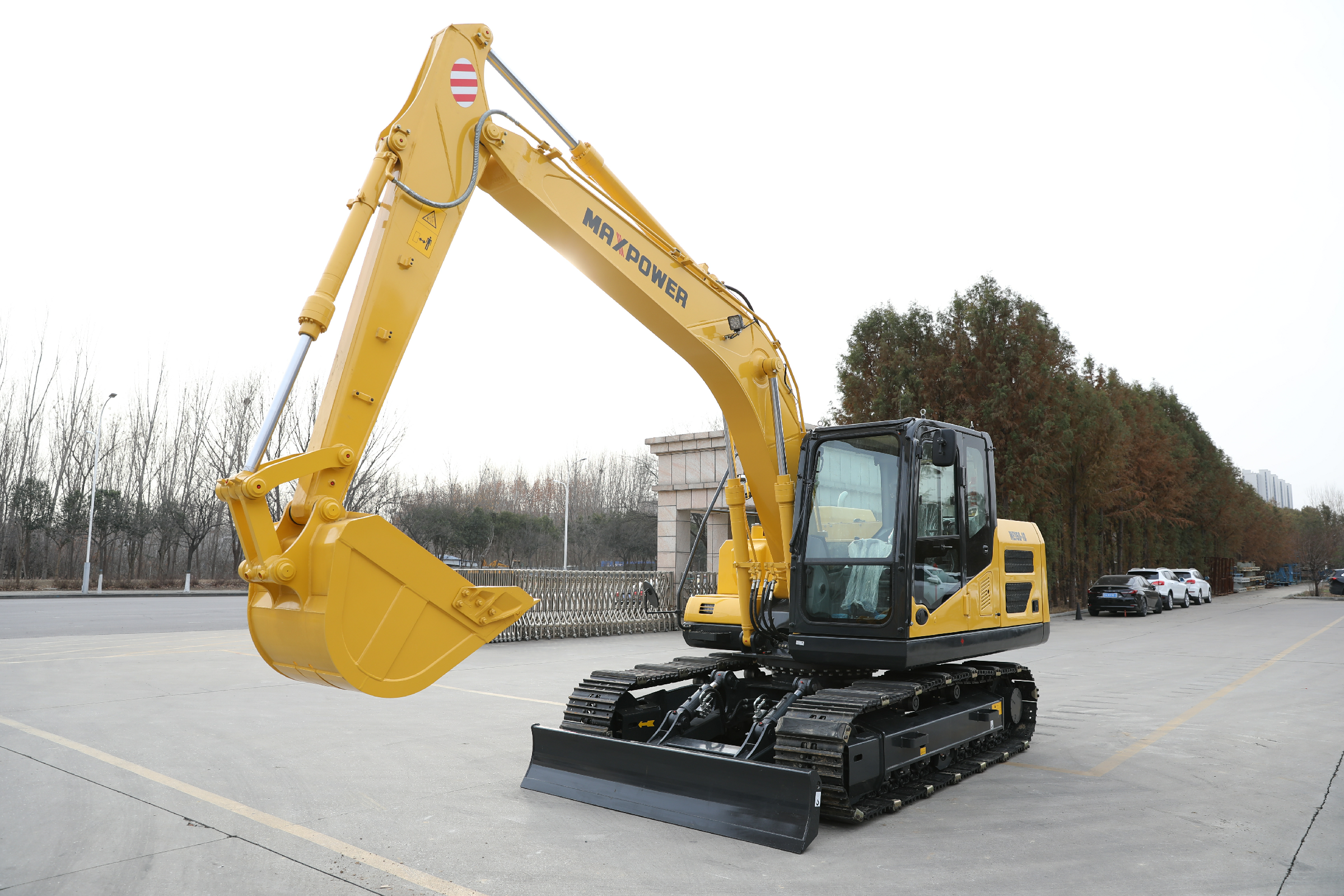
For a new machine enquiry, compare the MAXPOWER excavator range with your project requirements and request the current manufacturer load chart for the exact configuration. An excavator should be used for freely suspended loads only where the manufacturer permits that use and the project has a competent lifting assessment and suitable equipment.
A rated lifting chart applies to a defined machine, attachment arrangement, and set of conditions; a brochure maximum is not a universal lifting allowance.
Lifting radius is measured from the upper-structure rotation axis to the vertical load line, not from the front of the tracks.
Lift-point height and the suspended object's height are different measurements.
Over-front, over-side, and blade positions may have different rated capacities.
Load, rigging, coupler, bucket, and other attached-equipment weights must be counted according to the chart's stated basis.
A chart lookup is one part of a planned lifting operation, not a substitute for authorization, competent planning, or assessment of ground and site hazards.
Excavator lifting capacity is the manufacturer's rated load for a specified position and configuration, subject to the stated operating conditions. It is different from the maximum force that a hydraulic cylinder can generate or the weight that the machine might momentarily raise in an uncontrolled demonstration.
A rated load is determined using the applicable machine and testing framework. The published chart provides allowable values at defined lifting-point positions rather than an unrestricted total for the machine. A useful starting reference is Caterpillar's guide to finding excavator lift capacity.
A hydraulic limitation means a boom or arm circuit cannot develop the required lifting action at the specified geometry within its rated conditions. This is not the same as a counterweight or ground-stability issue, and a different position can change which limitation governs.
A stability limitation concerns the tendency of the machine to overturn as the external load creates a moment about its support. Radius, slew direction, undercarriage dimensions, ground condition, and permitted equipment configuration all matter.
Bucket breakout force and arm digging force describe forces during excavation. They cannot be converted into an approved suspended-load capacity by a simple shortcut. See the existing MAXPOWER guide to breakout force versus digging force for the distinct digging-force concepts; object handling requires the model's appropriate lifting information.
An excavator's working geometry changes through a lift. The required force, stability condition, and effective loading of its components also change, so manufacturers provide a matrix of lifting positions rather than one number for every task.
A suspended load produces a greater overturning moment as its horizontal distance from the rotation axis increases. Rated capacity therefore often falls at longer radii, but the exact relationship must be read from the actual chart rather than assumed from a general rule.
The lifting point follows the boom and arm geometry as it moves upward or downward. Two lifts with the same horizontal radius can have different permissible loads at different heights because the relevant hydraulic and stability conditions may differ.
Over-front and over-side ratings may differ because the working orientation changes the relationship between the load and the tracks or wheels. If a chart lists separate directions, use the value applicable to the complete planned lifting path.
A load may be within the chart at pickup but not at its furthest planned position. Review the actual range of lifting-point heights, radii, and orientations through the operation rather than checking only the starting position or destination.
The header and notes identify what the numerical entries mean. Before comparing two excavators, verify that their charts describe comparable configurations and use the same definition of lifting point and equipment weight.
Check the exact model, version, track or wheel arrangement, and the undercarriage condition specified in the chart. A narrow-track travel configuration, optional undercarriage, or different machine build may require a different chart.
Record the boom and arm lengths and the counterweight stated in the chart. A longer arm or optional counterweight changes the machine configuration, and an approval for one setup should not be transferred to another without the manufacturer's confirmation.
Look for the chart's stated lifting-point location and whether bucket, quick coupler, hook, and other fitted equipment are included. The chart might be based on a specified bucket-pivot point or an approved lift point on an attachment, so read its diagram before applying any deduction.
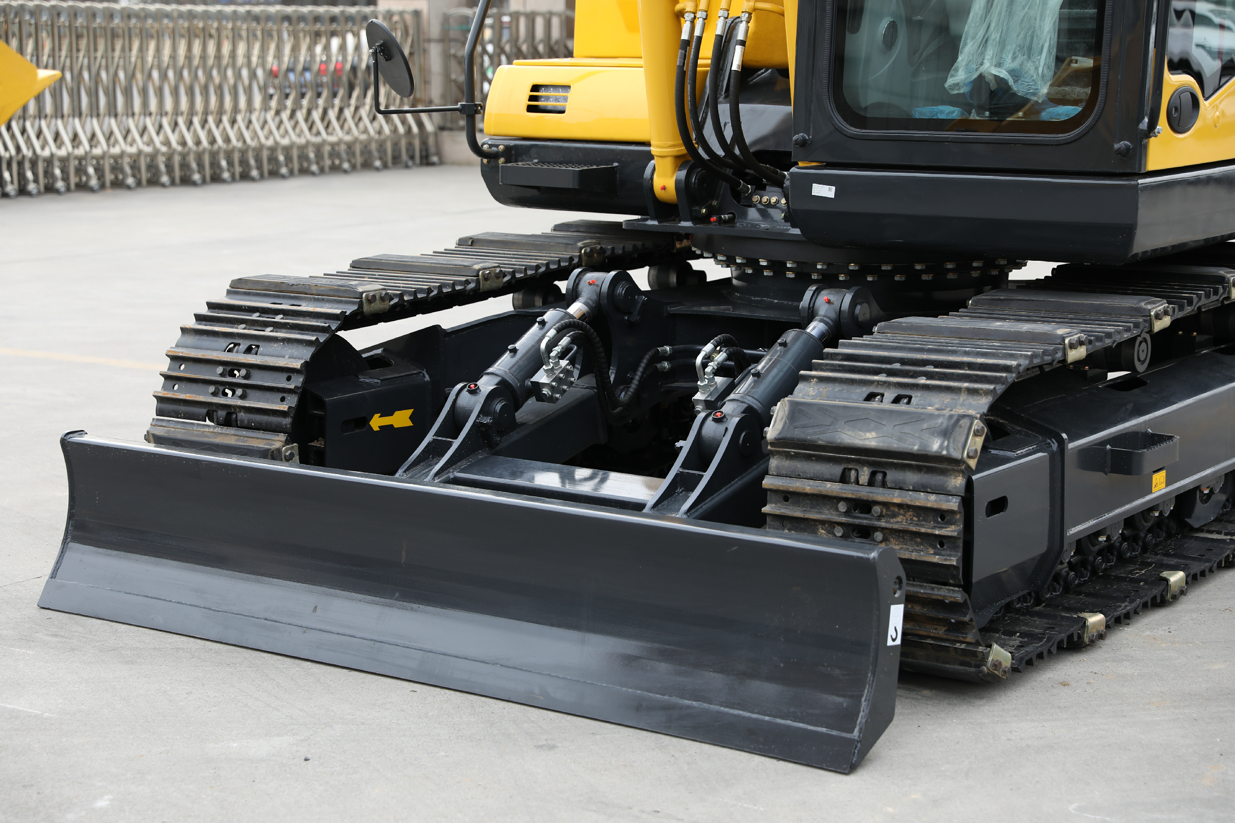
Compact excavator charts may distinguish blade raised from blade lowered. Wheeled or specialized machines may specify other stabilizing equipment. Use the stated arrangement only if the manufacturer permits it and the operation can maintain the required conditions.
| Chart field | Buyer should confirm | Why the field matters |
|---|---|---|
| Model and serial-range applicability | Exact machine and applicable chart revision | Prevents use of a chart for another version |
| Boom and arm | Installed lengths and linkage | Changes the geometry used for the rating |
| Counterweight and undercarriage | Specified weights, track width, or stabilizers | Affects stability and configuration |
| Load handling equipment | Lifting point, bucket, coupler, and options | Defines the chart's weight basis |
| Orientation | Over front, over side, or another stated sector | Selects the correct rating column |
| Blade or stabilizer position | Permitted and required position | May change which rating applies |
| Units and chart notes | kg, tonnes, lb, radius and height conventions | Prevents numerical misinterpretation |
The manufacturer's chart, not a generalized comparison article, is the controlling reference for the machine's rated load. Bobcat's lift-chart guide provides an example of how configurations and chart headings should be checked before selecting a capacity value.
The two basic coordinates in many excavator load charts are horizontal lifting radius and vertical lift-point height. Record them from the specified reference points, then locate the correct row and column.
Lifting radius is the horizontal distance from the excavator's rotation centerline to the vertical line through the lifting point or suspended load as defined by the manufacturer. Measuring from the front track edge, bucket teeth, or outer machine body can produce the wrong value.
Lift-point height is the vertical distance from the chart's reference ground plane to the manufacturer's specified lifting point. It is not necessarily the same as the height of the top or bottom of the object being carried.
A chain, sling, spreader beam, or other lifting accessory connects the object to the approved lifting point. Its dimensions influence the lift-point height needed to clear an obstacle or place the object, even where the object's final height is already known.
When lowering a component into a trench, the lifting point may remain above the ground while the object extends below it. Record the actual lifting-point path and the load geometry; do not use trench depth alone as the chart's lift-point height.
A chart can show different rated loads for the same radius and height depending on orientation. That difference is relevant when a load must be picked up in front of the machine and slewed to the side before being set down.
Use the chart's definition of the over-front sector and its stated blade or stabilizer condition. Do not infer that the front value applies through a complete 180-degree movement or to an unlisted orientation.
An over-side value may be lower where stability limits govern. The planned load must remain within the applicable manufacturer ratings throughout the operation, including any change from front to side.
If the intended path crosses several chart positions or orientations, examine all of them and identify the limiting one. The lowest applicable rating is an essential part of assessing the path, though other operating limits and site conditions may still rule out the lift.
A blade-down front rating cannot be borrowed for an over-side lift, a raised-blade condition, or a different machine. If the required configuration is not covered by the available information, request an approved chart or technical assessment instead of substituting a nearby number.
Many manufacturers mark entries to distinguish hydraulically limited values from stability-limited values. Caterpillar and Bobcat explain a common system in which a starred rating represents a hydraulic limit, while an unstarred rating may be governed by tipping stability.
Under the ISO 10567 methodology commonly referenced by manufacturer charts, rated capacity is constrained by a proportion of the static tipping load and a proportion of the applicable hydraulic lift capability. Published explanations often describe limits of 75% of tipping load and 87% of hydraulic capability for the specified static positions. These are rating principles, not user-selected multipliers for an arbitrary lift.
A published rated load may already include those margins. Multiplying it by 75% again would be an unsupported new value; dividing by 75% to infer extra capacity would be unsafe. Use the rated chart entry as provided and follow its notes.
Verify the symbol legend on the exact chart. Manufacturers may use symbols or formatting for other conditions, and a blank or missing chart entry must not be filled with an estimate based on neighboring cells.
Pick-and-carry operations introduce dynamic effects and may have different restrictions or ratings. WorkSafe Victoria explicitly distinguishes stationary static ratings from reduced dynamic allowances for travel; do not use a static table to authorize carrying a suspended load while moving. See its excavator lifting guidance.
The table below is fictional and exists only to demonstrate how rows and columns are interpreted. It is not a manufacturer's chart, a MAXPOWER rating, or permission to perform any lift. A real operation needs the applicable OEM chart and competent lifting plan.
Assume an imaginary machine has a chart showing the following values, in kilograms, for the same specified configuration. The values have no correspondence to any real excavator.
| Lift-point height | 3 m radius, front | 3 m radius, side | 4 m radius, front | 4 m radius, side |
|---|---|---|---|---|
| 0 m | 2,400 | 1,850 | 1,650 | 1,200 |
| +2 m | 2,100 | 1,600 | 1,400 | 1,050 |
| -2 m | 2,250 | 1,700 | 1,500 | 1,100 |
For a hypothetical lift-point height of +2 m at a 4 m radius over the side, the table entry is 1,050 kg. The 1,400 kg value in the adjacent front column is not interchangeable merely because the radius and height match.
If the same hypothetical load will move between front and side, and the lifting point changes height, every applicable segment needs a check. A single cell is not enough to approve the entire movement, and this illustrative table does not include the real machine's intermediate positions or other operating restrictions.
A real task may require a radius or height between published entries. Use the manufacturer's method or obtain the required technical confirmation; do not create an allowed capacity by averaging two cells unless that procedure is explicitly authorized.
The lifted object is only part of the weight assessment. Slings, chains, shackles, spreaders, attachments, and adapters may add load, while the chart may already account for selected installed components.
Obtain the actual item weight from a reliable specification or measurement and include any permanently fitted parts that form part of the suspended item. For a pipe, trench box, or fabricated component, use the correct configuration rather than a nominal catalogue description that excludes accessories.
Keep an itemized list of hooks, shackles, slings, beams, and other gear placed in the load path. Record their applicable ratings and weight using the lifting plan's requirements; the gear's own permitted working load is a separate limit from the excavator chart.
Check whether the lift chart includes a bucket, coupler, or approved lifting fixture. Add or deduct only the weights required by that chart's calculation basis and the manufacturer's instructions; do not automatically deduct every fitted component twice.
Suppose an imaginary chart's rated entry is 1,800 kg and its notes explicitly exclude lifting accessories and a separately installed fixture. An object of 1,500 kg, accessories of 90 kg, and a fixture of 80 kg produce a total of 1,670 kg for comparison under that simplified assumption. The 130 kg arithmetic difference is not a verified safety margin or approval: the real plan must also address geometry, orientation, component ratings, conditions, and every manufacturer limitation.
It may. A coupler adds an interface and may change the approved lifting point, geometry, assembly weight, and available working range. Some couplers include approved lifting points under defined conditions; not every coupling device or pin is a lifting point.
Ask for documentation identifying the permitted location and its rating for the intended lifting arrangement. Do not improvise a lifting connection at bucket teeth, unapproved pins, or other convenient-looking parts of the linkage.
The manufacturer's instructions may impose restrictions on the coupler position, attachment engagement, movement, or approved lifting equipment. These requirements exist in addition to the excavator's load chart and must be included in the complete assessment.
If the machine is supplied with a different bucket, quick coupler, long arm, or counterweight, request the revised lifting information or the manufacturer's approved adjustment method. A machine's compatibility with the coupler mechanically does not establish a lifting capacity for the new combination.
For buyers ordering several machines, record the coupler model, lifting-point data, operating instructions, and the chart revision associated with the supplied configuration. This avoids assuming all units of the same general size have identical lifting permissions.
A load chart is normally produced for defined reference conditions, commonly firm, level supporting ground. The actual site may have weaker ground, a trench edge, buried services, obstructions, or other factors that require a separate assessment.
Track contact area alone does not demonstrate that a working platform, slab, or excavation edge can support the machine and lifting operation. Ground conditions and the proposed position must be reviewed by competent project personnel using suitable information.
The machine's proximity to a trench can affect the stability and integrity of supporting ground. A lift above a trench must consider both the excavator's approved position and the excavation support and exclusion arrangements.
Plan for overhead conductors, structures, nearby machines, moving people, and the load's travel path. Keep people clear of suspended loads and make the signaling and supervision arrangements explicit.
A competent risk assessment can determine that an excavator is not the appropriate lifting appliance for the proposed task. HSE guidance on excavators and lifting operations notes that excavators are primarily earthmoving equipment and that lifting requires suitable equipment and additional controls. Apply the requirements governing the project location.
A chart answers a numerical question for a rated configuration. A lifting plan addresses whether the machine may perform the operation, how the load will be secured and controlled, and how foreseeable site risks will be managed.
Before relying on any chart, confirm that the machine is designed and approved for freely suspended loads in the intended application. A published lifting figure does not automatically authorize object handling or all related activities.
The responsible team should assess site conditions, load path, rigging, signals, personnel exclusion, communication, emergency arrangements, and the conditions under which the operation must stop. The UK's HSE guidance on lifting operations explains the importance of competent planning and suitable supervision.
Lifting rules, examinations, operator qualifications, alarms, check valves, and inspection requirements vary by jurisdiction and equipment. Ask the supplier for documents relevant to the destination market and have the local responsible professional identify the applicable obligations.
The explanations here help buyers understand documentation and prepare enquiries. They do not replace the original operator manual, the relevant regulatory requirements, or a site-specific lifting assessment.
A useful comparison starts with the job rather than a brochure's largest capacity figure. Describe the object and the complete path, then ask each supplier for a rating applicable to the same conditions.
Record approximate pickup, transfer, and placement positions for competent technical review. The project should provide required lifting-point height, radius, orientation, and relevant changes along the path, without guessing a final rated capacity.
An apparent advantage may disappear when one proposal uses a different boom, arm, bucket, counterweight, or undercarriage. Compare the configurations actually offered and the chart revisions that apply to them.
An excavator selected for trenching might also be needed for pipe placement, but digging productivity and lifting suitability remain distinct questions. Review the two duties separately, then assess whether one permitted equipment configuration meets both.
For MAXPOWER machines such as ME210.9, ME260.9, or ME390, the associated plan identifies them as potential product families for obtaining documents, not verified lifting capacities. Do not publish model-specific lifting figures without an authenticated chart for the specific version and configuration.
A complete enquiry reduces back-and-forth between the equipment buyer, manufacturer, and lifting planner. Use the following checklist to obtain the right documents and make unresolved items visible.
| Enquiry item | Information to supply | Confirmation or document to request |
|---|---|---|
| Intended lifting task | Object, dimensions, known mass, purpose and placement | Manufacturer permission for the intended object-handling application |
| Machine | Model, serial number or proposed build, undercarriage | Current applicable load chart and operating manual |
| Working equipment | Boom, arm, counterweight, bucket, coupler, options | Chart basis and approved configurations |
| Lifting geometry | Pickup, transfer and set-down positions; height, radius, direction | Rated loads for all relevant chart positions and conditions |
| Lifting arrangement | Proposed lifting point, accessories and their weights | Approved connection and component ratings |
| Site conditions | Ground and edge conditions, slopes, nearby structures and hazards | Requirements for competent site assessment and any restrictions |
| Operating controls | Country and applicable work requirements | Required indicators, protective devices, inspections and training |
| Documentation | Chart revision, certificates where required, technical contact | Traceable handover and confirmed outstanding items |
If a load's weight, a model's over-side rating, or the included bucket mass is unknown, identify the gap explicitly. Do not fill it with a guessed value, a machine from another brand, or a nearby chart entry.
Retain the exact chart, machine and lifting-equipment identities, approved configuration, and applicable instructions with the project records. Update the assessment if the machine or lifting arrangement changes.
The buyer should request confirmation of whether the manufacturer permits the proposed application and which documentation applies. The competent lifting team then decides whether the actual site plan can be carried out safely or requires a different method or machine.
It is the rated load permitted at a specified lifting-point radius, height, direction, and machine configuration under the manufacturer's stated conditions. It is not one constant weight for every boom position or a conversion of digging force. Use the current load chart and confirm the excavator is approved for the intended lifting task.
First match the chart header to the actual machine, boom, arm, undercarriage, and equipment. Identify the required lift-point height, horizontal radius from the slew axis, and lifting direction, then find the relevant chart entry. Read every note and include rigging and attachment weight as its stated basis requires.
It often decreases as the horizontal lifting radius becomes larger because the load creates greater overturning leverage. The exact rated value also depends on lift-point height, orientation, and hydraulic limits. Do not calculate a new permissible load from a simple distance ratio; use the corresponding manufacturer chart entry.
It may be, depending on the excavator and its rated configuration. Many charts distinguish front and side sectors, and some compact machines also distinguish blade-up from blade-down positions. Check the values covering the entire planned path rather than carrying the highest front value through a side slew.
On many manufacturer charts, an asterisk identifies a rating governed by hydraulic capability rather than tipping stability. Symbols are not universal, so the legend on the exact chart controls their interpretation. Neither marked nor unmarked values authorize a lift outside the specified configuration, conditions, or approved use.
That depends on the chart's documented basis. Some ratings assume a particular attachment or lifting-point condition, while others require deductions for equipment not included. Identify the supplied bucket, coupler, lifting fixture, and rigging, and follow the manufacturer's stated method so a component is neither omitted nor counted twice.
It may be possible where the manufacturer permits object handling and the machine, lifting point, rated chart, ground, rigging, and lifting plan suit the job. Pipe mass alone is not enough: the load may move through several radii and heights. The competent team must assess the whole operation and may choose different lifting equipment.
Do not assume so. Moving with a suspended load introduces dynamic effects and can require a different rating or be prohibited by the manufacturer's instructions. Obtain explicit permission and the applicable travel-lift limits, and have a competent planner assess the operation. A stationary over-front figure does not authorize pick-and-carry work.
Not at every comparable position. Rated capacities depend on the specific boom, arm, counterweight, undercarriage, orientation, and lifting geometry as well as machine size. Compare authenticated charts at the same task conditions. A larger operating weight or higher breakout force does not by itself establish the allowable suspended load.
Provide the intended machine and equipment configuration, the object's documented weight and dimensions, proposed lifting point and rigging, and the pickup-to-placement geometry. Include site ground conditions and destination-market requirements. Request the exact applicable chart, manufacturer permission, and confirmation of outstanding technical items.
Excavator lifting capacity is meaningful only when it is tied to the exact rated configuration and lifting position. A good equipment enquiry records the complete lifting task, identifies which weights and conditions are included, and obtains the appropriate original chart before any capacity judgment is made.
Send the project requirements to MAXPOWER when reviewing the excavator product range. Request the model-specific load chart, permitted lifting configuration, and relevant operating documents. A competent lifting planner must then assess whether that equipment is appropriate for the actual site or whether another lifting solut