Maxpower Construction Machinery Manufacturer




A contractor may want one excavator to change between a digging bucket, grading bucket, and hydraulic attachment during the same shift. A quick coupler can make that arrangement practical, but only when the machine, coupler, attachment interfaces, and controls work together. An excavator quick coupler compatibility check should establish that complete match before the order is finalized.
The first questions are straightforward: which excavator is being supplied, which coupler will be installed, and which attachments must it handle? The answers should lead to drawings, approved combinations, operating instructions, and a clear handover record. A matching pin diameter or a statement that the coupler is “universal” is not enough by itself.
If you are specifying a new equipment package, send MAXPOWER the intended attachment list and any existing bucket drawings. Review the excavator range, then request confirmation of the coupler arrangement available for the exact machine and order.
Check the machine-to-coupler connection and the coupler-to-attachment interface separately.
Identify the exact models and interface specifications; a broad tonnage class is only a starting point.
Confirm how locking, additional retention, and operator indications work on the supplied system.
Product names such as hydraulic, automatic, or semi-automatic do not consistently describe the same functions across manufacturers.
Include coupler weight, added geometry, working clearance, and approved tasks in the equipment assessment.
Retain the approved attachment list, installation record, operating instructions, and inspection requirements.
Excavator quick coupler compatibility covers more than whether two parts can be connected. It includes the interfaces, the locking arrangement, the machine installation, and the intended use of the completed assembly.
At the top of the coupler, the mounting arrangement must suit the excavator arm and linkage. At the bottom, the coupler must engage the specified attachment interface correctly; those two sets of dimensions should not be mixed together. steelwrist.com
Describe the attachments and tasks the machine will perform, including any use of tilt equipment or other intermediate devices. Approval for one bucket or task should not be treated as permission for every tool that appears to fit.
| Check | Information to obtain | What the confirmation should establish |
|---|---|---|
| Excavator identity | Model, serial number or build specification, arm, and linkage | The coupler's upper mounting arrangement suits the actual machine |
| Coupler identity | Manufacturer, model, size, version, and serial number where available | The proposal refers to a defined product and installation |
| Attachment interface | Approved drawing, interface code, and relevant dimensions | Each tool can engage the coupler as intended |
| Locking and retention | Description of the lock and any additional retention system | The complete securing arrangement is understood |
| Controls and indications | Control kit, operator signals, and fault instructions | The supplied machine can operate the coupler correctly |
| Powered attachments | Required oil and electrical connections | Attachment services are compatible with the installed equipment |
| Weight and geometry | Coupler, adapter, tilt equipment, and attachment details | The complete assembly is suitable for the intended work |
| Inspection and support | Manuals, inspection criteria, approved parts, and service contacts | The owner can maintain the configuration in service |
For an overview of the tools that may appear on the attachment list, see the mini excavator attachments guide. Use the checklist above to assess the connection and approval requirements for each selected tool.
The same model name can cover different production versions or equipment configurations. Record what is actually installed, especially when a used machine has a replacement arm, altered linkage, or an existing coupler of uncertain origin.
Provide the machine model and serial number together with the relevant build information. Photographs can help the supplier identify the arrangement, but a photograph should support rather than replace the required measurements and documents.
Record the manufacturer's identification plate and the exact coupler designation. Different sizes, generations, or control packages within one product family may require different parts and instructions.
List each bucket or powered tool with its model, interface, and known modifications. An existing fleet described only as “three buckets and a breaker” leaves the supplier without enough detail to confirm the combinations.
If a plate is missing or an attachment has been modified, mark that item as needing technical identification. Do not fill the gap by assuming that it is equivalent to a nearby tool with a similar appearance.
Terms such as pin grabber, dedicated coupler, and S-type help describe products, but manufacturers do not always use the categories in exactly the same way. For excavator quick coupler compatibility, the decisive information is the specified interface and its approved geometry.
A coupler that captures attachment pins must suit the documented pin diameters, spacing, width, and other engagement requirements. A variable pickup range can accommodate certain differences, but that range still has defined limits. uk.millergroundbreaking.com
Some attachments are built around a named interface size and a specific bracket geometry. Obtain the applicable drawing and version rather than treating a shared interface name as confirmation that every mechanical feature and service connection will match.
A manufacturer may describe a dedicated interface using pin-grabber terminology because pins are part of that design. Avoid deciding compatibility from the category name alone; ask the supplier to identify the actual mating surfaces and engagement requirements. Caterpillar
If an adapter is proposed, include it in the approval and configuration record. Its connections, added weight, geometry, and permitted use become part of the complete assembly that needs assessment.
Dimensions are essential evidence, but they do not establish the whole excavator quick coupler compatibility decision. The correct values must refer to the correct interface and come with the manufacturer's tolerances, condition criteria, and installation requirements.
For a pin-based arrangement, record the relevant pin diameters and centre-to-centre distances using the supplier's drawing convention. A coupler advertised with variable pin centres still needs the actual attachment to fall within its approved geometry.
The width between mounting features and the space available for the coupler body both matter. Check the drawing for the required clearances around the bracket, locking mechanism, and any additional retention features.
A nominal dimension does not show whether a contact surface is damaged, worn, obstructed, or incorrectly shaped. Where the attachment has been repaired or altered, provide that information for assessment before it enters the approved list.
Machine mounting pins, attachment pickup pins, and retaining devices serve different purposes. Use the specified parts; do not select a substitute solely because it passes through the hole. Geith Excavator Attachments
If a tool does not fit, obtain the approved solution or select a suitable alternative. Drilling, grinding, welding, changing pins, or adding improvised spacers can change the connection and should not be treated as routine purchasing adjustments.
Automation terminology varies between suppliers. Break the description into the functions it covers: moving the lock, securing the attachment, confirming engagement, and connecting any hydraulic or electrical services.
A manually operated system requires the operator to complete the specified mechanical actions and checks. The exact locking device and any retaining component should be identified in the instructions for that product.
A hydraulic mechanism moves part of the locking arrangement through the installed circuit. That description alone does not explain whether a separate manual retaining step is required or whether the tool's oil hoses connect automatically.
In some safety guidance, semi-automatic describes a hitch requiring a manually fitted retaining pin. A supplier may use similar terminology for a different division between automated locking and manually connected tool services, so request an explicit description of the required actions. HSE
| Function | What to establish | What the product name does not prove |
|---|---|---|
| Lock actuation | How the lock moves and what controls it | Whether all securing steps are completed automatically |
| Additional retention | Which device or arrangement prevents unintended release in the specified circumstances | Whether a separate manual action is required |
| Engagement indication | What the visual or electronic signal actually detects | That every necessary engagement check has been completed |
| Hydraulic connection | Whether tool oil connections are manual or automatic | That a hydraulic locking mechanism also connects the hoses |
| Electrical connection | Which connectors and signals are provided where needed | That an attachment's controls are compatible merely because it mounts |
Ask the supplier to state which changeover actions remain manual and which are performed through the machine controls. This makes proposals easier to compare and gives the operator a clear basis for training.
A useful excavator quick coupler compatibility review considers the entire securing arrangement. The aim is to understand what is supplied, what conditions it is designed to manage, and how correct engagement is confirmed.
Obtain the manufacturer's explanation of how the attachment is held in the working position. Ask which components must be engaged and how the operator verifies that condition on the exact coupler.
Depending on the design, additional retention may involve a specified pin, catch, mechanical lock, or another arrangement. Confirm the function and limitations of the supplied design rather than assuming that a familiar marketing term describes every feature.
For a hydraulic system, request the documented behavior if supply pressure is lost and the actions required when a fault is detected. Any verification of fault behavior should follow the manufacturer's commissioning procedure and be handled by competent personnel.
A signal may relate to a particular pin, sensor, pressure condition, or lock position. Establish exactly what it confirms and which other checks the manual still requires; do not infer complete engagement from a signal whose function has not been explained.
The manufacturer's procedure should define the confirmation steps before work and after attachment changes. Do not turn a check demonstrated for one coupler into a universal method for a different design.
The UK's HSE guidance on quick hitches emphasizes competence with the specific hitch, use of the prescribed retaining parts, and checks after changes. These are useful procurement questions when assessing how the supplied system will be operated and supervised. HSE
For a powered coupler, excavator quick coupler compatibility includes the installation kit and control system. A suitable mechanical body can still be an incomplete package if the machine lacks the specified valves, controls, wiring, or monitoring equipment.
Obtain the coupler manufacturer's circuit requirements and have them checked against the proposed machine installation. Do not infer the correct locking supply or plumbing arrangement from the excavator's general auxiliary-attachment specification.
Confirm the controls needed to engage or release the coupler and the indications provided to the operator. The supplier should explain any specified interlocks, warnings, and fault responses as part of the complete installed system.
Record the kit, controller, and applicable configuration information used for the installation. If an existing machine has modified wiring or an older control system, resolve compatibility with the responsible supplier before commissioning.
The circuit that operates a coupler lock does not establish that a breaker, auger, or rotating tool can run correctly. Check the powered attachment's operating requirements separately from the coupler's locking and control requirements.
A coupler can lock an attachment hydraulically while the operator still connects the tool's hoses by hand. Automatic oil or electrical connection is a further function that requires a suitable interface on both sides. steelwrist.com
For an automatic connection system, obtain the approved combination of coupler and attachment-side components. Matching requirements can include connection size, position, number, and the specified electrical connector where one is used.
A bucket that needs no oil supply and a hydraulic tool with several service connections present different requirements. Verify every tool's actual arrangement instead of assuming that successful attachment of the bucket proves compatibility for the entire fleet.
Ask how the interfaces must be kept clean, protected, and inspected under the manufacturer's instructions. Identify any model-specific protective features required even on mechanical tools used with the automatic system.
If cross-brand interchangeability is part of the proposal, ask for the applicable compatibility documentation and its conditions. Check the exact products and versions, including the function of the retention system and any oil or electrical connections. Steelwrist
The coupler becomes part of the excavator's working assembly. Its weight and geometry, together with the attachment and any intermediate equipment, must be considered when checking the approved configuration.
Record the coupler, adapter, tilt equipment, and attachment details together. Comparing only the bare bucket weight can leave part of the actual assembly out of the assessment.
Where lifting is intended and permitted, use the manufacturer's information for the actual machine configuration, load position, and lifting arrangement. Read the chart's basis before applying any weight adjustment; a component already included in that basis should not be counted again. volvoce.com
An approved coupler lifting point has its own rating and conditions. Those limits do not replace the excavator's applicable load information or the limits of the rest of the lifting arrangement. geith.com
The assembly may fit in one position yet interfere with the machine elsewhere in its permitted movement. Have the installer check the required clearances around the attachment, coupler, linkage, cylinders, arm, and hoses according to the relevant instructions. geith.com
An additional device changes the assembly and introduces further interfaces and operating requirements. Confirm the whole combination and intended tools rather than assuming that separate approval of each component establishes approval of the stack.
An excavator quick coupler compatibility review should therefore include an operating-envelope assessment. It should not promise a universal change in digging force, lifting capacity, or reach from the coupler name alone.
A practical fleet record links each permitted tool to the machine and coupler combinations that have been assessed. This becomes especially useful when attachments move between sites or operators use several machines during a week.
Use machine, coupler, and attachment identification numbers alongside the applicable drawing or approval record. Include any operating conditions that apply to the combination so the list carries more information than a simple yes-or-no label.
A tool awaiting measurements or manufacturer assessment should remain clearly identified as an unresolved item. Keep it separate from the approved working list until the necessary evidence is available.
Suppose one proposal covers all existing buckets while another requires new brackets on some of them. Ask for the affected attachments, approved conversion scope, revised configuration information, and verification requirements to be identified before selecting the package.
Similar paint, bucket width, or pin size can make two attachments look interchangeable. Clear identification and current records help the operator select an assessed combination without relying on memory or appearance.
The handover should connect the purchasing decision to the equipment actually supplied. Ask the responsible installer to document the completed checks using the applicable manufacturer procedures and the final machine, coupler, and attachment identities.
| Record item | Information to retain | Purpose |
|---|---|---|
| Equipment identity | Machine, coupler, and attachment models and serial numbers | Identifies the exact supplied combination |
| Interface evidence | Approved drawings, dimensions, and accepted attachment list | Connects the physical installation to the agreed specification |
| Securing arrangement | Main lock, additional retention, and prescribed retaining parts | Describes the complete attachment-holding system |
| Control installation | Specified kit, circuit, controls, indicators, and applicable configuration | Confirms that the required functions are included |
| Functional verification | Results of the manufacturer's installation and engagement checks | Records whether the supplied arrangement meets its requirements |
| Working clearance | Required movement and hose-clearance checks | Identifies interference concerns before use |
| Weight and permitted work | Assembly configuration, applicable load information, and restrictions | Defines the scope of the intended application |
| Operator handover | Correct manuals, familiarization, and required confirmation procedure | Supports operation of the specific coupler |
| Service information | Inspection criteria, approved replacement parts, and support contacts | Supports maintenance after delivery |
Have competent personnel carry out the specified installation and functional checks. A demonstration that the coupler can pick up one bucket does not, by itself, verify every listed attachment or every required retaining and control function.
Where the destination market or project requires particular declarations, standards, or inspection documents, obtain the documents applicable to the supplied product and installation. A general certificate or catalogue statement should not be treated as confirmation of every proposed machine-and-attachment combination.
Supply instructions in a form the intended users can understand, together with the approved attachment list and the relevant checks. For rental or shared equipment, explain how this information reaches the next operator when the machine changes hands.
Excavator quick coupler compatibility is established for a configuration and condition that must be maintained. Wear, damage, changed components, or an altered attachment bracket can create questions that the original purchasing record does not answer.
Use the manufacturer's inspection requirements for the actual coupler and controls. Depending on the design, these may cover engagement surfaces, retaining parts, structural condition, hydraulic connections, indicators, and sensors.
Keep the date, equipment hours where relevant, observed condition, work completed, and responsible person. If a locking, retention, or control fault is found, follow the manufacturer's fault instructions and have it resolved before returning the equipment to use.
A replacement bracket, changed pin, different control kit, or additional adapter may alter the approved arrangement. Confirm the suitability of the revised configuration and update the attachment record when a relevant change is made.
Ask how routine inspection points and identification marks can be accessed on the installed machine. This helps the owner assess whether the specified inspection and cleaning tasks can be carried out as intended.
The NIOSH guidance on excavator quick coupler attachments emphasizes following the instructions for the actual brand and model, completing connection checks, and maintaining the equipment. Carry those requirements into the operator handover and service records. cdc.gov
For an existing MAXPOWER machine, review the repair and maintenance support and provide the machine identity, coupler details, attachment information, and relevant photographs when requesting assistance.
It means the machine, coupler, attachment interface, controls, and intended task form a suitable combination. Both the machine-side mounting and the attachment-side connection need assessment. Obtain the relevant drawings, approved configuration, operating instructions, and verification record for the actual equipment.
No. Pin spacing, mounting width, engagement geometry, clearances, component condition, and the intended use also matter. The relevant dimensions differ between the machine and attachment sides. Have the supplier check the full interface against the coupler's drawings and permitted configuration, not just one measurement.
No universal label should be taken as approval for every tool. A coupler may accept a defined range of pin dimensions or several specified interfaces, but its limits still apply. Identify each attachment and request confirmation of the complete combination, including retention, clearance, weight, and any service connections.
Not necessarily. Hydraulic may describe how the locking mechanism moves, while automatic can refer to locking, tool-service connections, or both. Terminology differs between suppliers. Ask which actions remain manual, whether retaining steps are required, and whether hydraulic and electrical connections engage automatically.
That depends on the specific design, its condition, and the circumstances described by the manufacturer. Request the documented retention behavior and fault instructions for the supplied system. Do not assume that all hydraulic couplers release, or that every automatic coupler remains secure under every failure condition.
Only follow the confirmation procedure specified for the actual coupler and control system. An indicator detects a defined condition and may not answer every engagement question. Ask what each signal means and complete all required checks before use; an unexplained light or alarm is not evidence of a verified connection.
Possibly, if each bucket's interface, condition, and intended use are approved for the proposed combination. Submit identification, dimensions, photographs, and any repair or modification history. If an adapter or replacement bracket is needed, include its approved installation, weight, geometry, and verification in the proposal.
The coupler and associated equipment form part of the working assembly. Use the load information and restrictions for the actual machine configuration and lifting arrangement. Check what the chart already includes before making adjustments, and assess the approved lifting point separately; its rating is not the machine's capacity.
Only after the complete arrangement has been assessed for the intended use. Each additional device introduces another interface, weight, geometry, control, and clearance requirement. Provide the full equipment list and obtain confirmation of the specific stack rather than relying on separate component descriptions.
Send the excavator model and serial number, coupler identification, attachment list, interface drawings, and photographs. Include known modifications, intended tasks, and any oil or electrical connection requirements. Ask the supplier to identify the approved combinations, installation scope, and handover checks in writing.
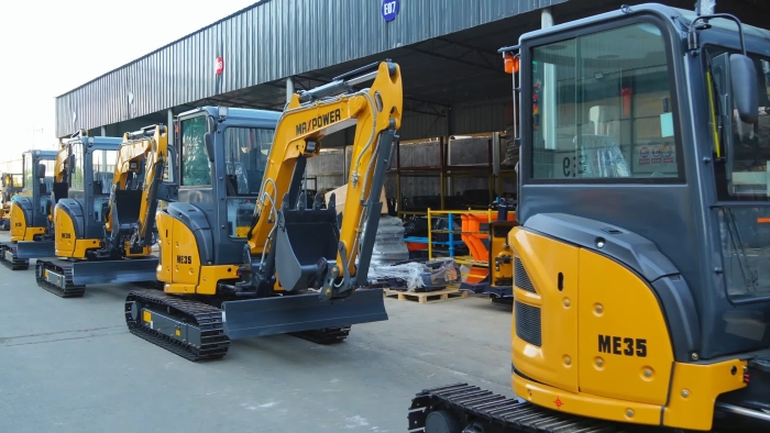
An excavator quick coupler compatibility checklist is most useful when it produces a clear record of the equipment that can work together. Confirm the two connection interfaces, the securing system, the controls, and the permitted use, then retain the evidence with the machine documents.
Share your attachment list and operating requirements with MAXPOWER. Compare the available excavators, then request confirmation of the coupler configuration, approved attachment combinations, and handover scope for the exact model before finalizing the order.