Maxpower Construction Machinery Manufacturer




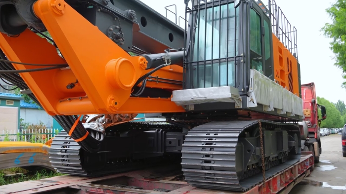
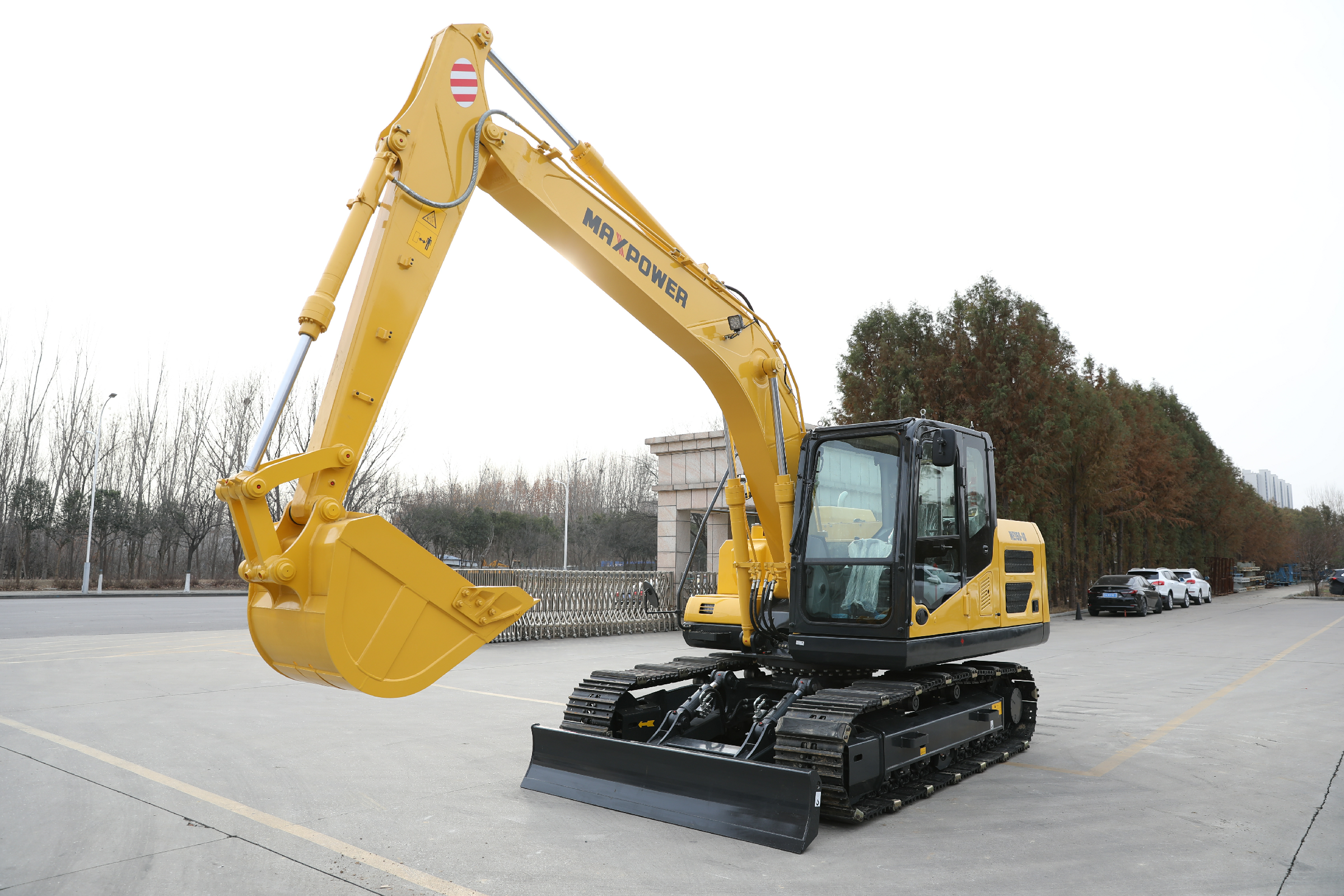
A compact excavator may pass through the site entrance and still have too little room to complete the job. Once the upper structure turns, the rear of the machine can move toward a wall, fence, parked vehicle, or another part of the work area. That is why mini excavator tail swing deserves its own check before a purchase.
Zero tail swing is worth considering when rear clearance repeatedly limits machine positioning. Conventional tail swing can also suit the project when the site accommodates its rear movement and the complete machine meets the workload. The useful comparison is between documented dimensions, configurations, and tasks.
If you are comparing machines for a restricted site, send MAXPOWER a measured sketch, photographs, and the intended attachment list. Start with the excavator range, then request the dimensional drawing for the exact model and configuration under consideration.
Zero tail swing describes the rear upper structure in a specified configuration; it does not describe every moving part of the excavator.
Tail swing radius and rear overhang are different measurements.
A machine can have a narrow access width and require a wider approved configuration for work.
Conventional, reduced, and zero tail designs should be compared using actual dimensions.
Lifting capacity, attachment suitability, visibility, and service access require separate checks.
A useful site sketch includes the excavation, machine position, obstacles, spoil handling, and people routes.
Mini excavator tail swing describes the movement of the rear upper structure as the excavator slews above its undercarriage. Buyers use the term to discuss how much rear clearance a machine needs, but a specification may express this as a radius or as overhang beyond the tracks.
Tail swing radius is the horizontal distance from the slewing center to the outermost rear point of the rotating upper structure. The reference point is the center of rotation, so a zero tail machine still has a measurable tail radius.
Rear overhang is the distance that the rotating rear extends beyond the relevant track boundary. It helps explain why two excavators with similar track widths may need different amounts of space beside the undercarriage.
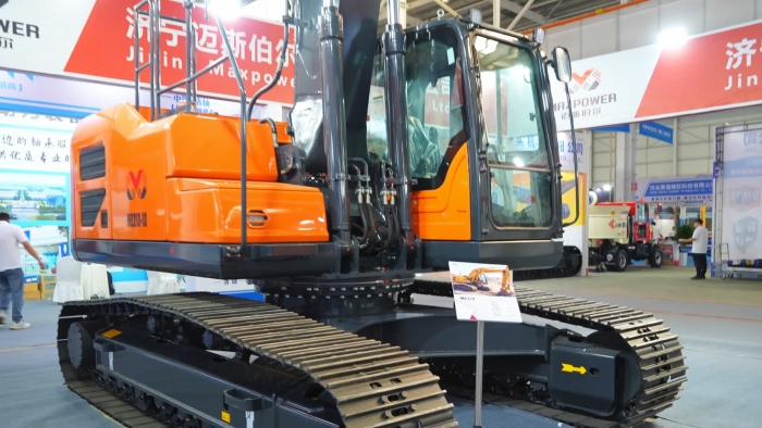
A zero tail design keeps the rear upper structure within the track width during rotation in the manufacturer’s stated configuration. Confirm which track position, counterweight, and fitted equipment that description covers. kubotausa.com
Where the undercarriage is adjustable, the advertised access width and the width associated with zero rear overhang may differ. Request both dimensions and the operating instructions for each approved configuration.
A conventional design has a rear upper structure that extends beyond the tracks during part of its rotation. That projection must be included when assessing machine positions beside obstacles.
A reduced or short tail design generally limits rear projection while retaining some overhang. Terminology varies, so compare the stated dimension instead of assuming that every manufacturer uses the same boundary between categories. Bobcat Company
The first useful mini excavator tail swing question is therefore simple: which measurement is the supplier quoting, and what configuration does it describe?
Use the following comparison to decide what information to request. It is a purchasing framework, not a performance ranking for individual models.
| Selection point | Zero tail swing | Conventional tail swing | What to verify |
|---|---|---|---|
| Rear movement | Rear remains within the stated track width | Rear projects beyond the tracks | Dimensioned rear rotation drawing |
| Work beside obstacles | Can reduce the rear space needed for a proposed position | Requires room for the rear projection | Actual obstacle locations and required clearance |
| Narrow entrances | Access still depends on overall travel dimensions | Access still depends on overall travel dimensions | Width, height, length, and route geometry |
| Lifting suitability | Depends on the individual machine and configuration | Depends on the individual machine and configuration | Matching load charts and approved lifting arrangement |
| Operator space | Must be assessed on the actual cab or canopy | Must be assessed on the actual cab or canopy | Entry, legroom, controls, and visibility |
| Service access | Depends on panel layout and component placement | Depends on panel layout and component placement | Access to inspection and maintenance points |
| Main purchasing question | Does reduced rear projection solve a recurring site restriction? | Can the site accommodate the rear sweep while the machine meets the task? | A measured site layout and an exact specification |
A reduced tail model sits between the first two descriptions geometrically, but its usefulness still depends on the measured overhang. There is no need to reject it simply because the brochure does not use the word zero.
A gateway tells you whether the machine can pass one section of the access route. It does not show the space available when the excavator turns, reaches toward the trench, or transfers material to another location.
For a useful mini excavator tail swing assessment, separate the access survey from the working layout. On the access survey, record narrow openings, bends, overhead restrictions, and the proposed travel configuration. On the working layout, mark where the tracks will stand and where the upper structure, front equipment, and material will move.
For an example of the access questions involved, see the mini excavator width and site access guide. Keep its model-specific dimensions separate from the drawing for your proposed purchase.
A wide entrance can lead directly into a restricted corner, while a narrow entrance may open into a large yard. Include the transition between the entrance and the work area when asking the supplier to assess suitability.
Consider where excavated material will go and how replacement material will arrive. A machine position that allows digging may still leave an awkward or obstructed route for loading and material handling.
A dimensioned drawing is more useful than a photograph for checking mini excavator tail swing. Ask for a top view showing the slewing center, track boundaries, rear outline, and the configuration used for the measurements.
Check whether a quoted number is a radius, a diameter, or an overhang. Also confirm that the track width means the distance between the outer edges, rather than the spacing between track centerlines.
For an idealized machine with the slewing center on the undercarriage’s width centerline, maximum lateral rear overhang can be illustrated as:
Rear overhang = max(0, tail swing radius - overall track width / 2)
This is a geometric illustration for understanding a drawing. It is not a method for establishing safe operating clearance or approving a machine position.
The following dimensions are invented examples, not MAXPOWER product specifications. Both examples assume a centered slewing axis, and only the rear upper structure is being compared.
| Measurement | Example A | Example B |
|---|---|---|
| Overall track width | 1,500 mm | 1,500 mm |
| Tail swing radius | 750 mm | 1,100 mm |
| Half of track width | 750 mm | 750 mm |
| Calculated maximum lateral rear overhang | 0 mm | 350 mm |
| Diameter of the rear sweep circle only | 1,500 mm | 2,200 mm |
Example B requires allowance for a rear sweep extending 350 mm beyond the track side. Example A has no rear overhang under these assumptions, but its boom, bucket, and other components still require their own assessment.
Doubling the tail radius describes the diameter of the rear sweep circle. It does not include the full movement of the front equipment, attachment, load, or the clearance required by the site plan.
Suppose the first hypothetical machine’s width changes from 1,500 mm to 1,000 mm while its 750 mm tail radius remains unchanged. Under the same centered-axis assumption, the calculated rear overhang becomes 250 mm.
The arithmetic explains why a brochure label cannot replace configuration checks. It does not establish whether that narrower configuration is approved for excavation, rotation, or lifting; the machine’s instructions must answer those questions.
Give a zero tail model close consideration when rear clearance repeatedly prevents a useful working position. Begin with the site restriction, then assess whether the proposed machine resolves it without creating another limitation.
For a trench running along a wall, identify the required trench line and the available machine positions. Reduced rear projection can be useful, but the front working geometry must also allow the attachment to reach the intended excavation.
The rear movement and the boom’s offset capability are separate checks. Ask for both drawings if the task requires excavation close to a structure.
In an established garden, map retaining walls, fences, trees, and structures that constrain machine placement. Compare the proposed rear sweep against those fixed features before deciding which layout works.
Also plan the material route. An excavator positioned neatly between two obstacles may still require a different arrangement to transfer soil into a dumper or reach the planned spoil location.
Where a work area is bounded by barriers or other restrictions, show those boundaries on the site sketch. Assess the complete operation within the approved arrangement, including front equipment and material handling.
A smaller rear sweep should not be treated as permission to operate closer to passing traffic or people. The traffic and work-area arrangements need their own assessment.
If crews repeatedly reposition because the rear approaches an obstacle, record those interruptions during a representative job. That evidence can help determine whether a different mini excavator tail swing layout would improve the working arrangement.
The likely benefit is specific to that task. A demonstration should establish whether the proposed model reduces those interruptions while still reaching, digging, and unloading as required.
Conventional tail swing remains a reasonable option when the site provides space for the documented rear sweep. Compare the complete machine against the work rather than excluding it at the category stage.
On a spacious site, rear overhang may not determine the machine position. You can then compare the actual digging envelope, attachment compatibility, service arrangements, and other requirements without making tail type the deciding factor.
A contractor may have repeat projects with consistent machine positions and material routes. If the proposed rear sweep fits those layouts, ask whether a different design would solve any remaining operational problem.
An individual conventional model may match the required reach, attachment, or service arrangement well. That conclusion should come from its specification and assessment, rather than a general claim that conventional machines are stronger or easier to maintain.
For a wider purchasing checklist, use the guide to choosing a mini excavator for construction projects. This tail-swing comparison addresses the spatial part of that decision in greater detail.
Mini excavator tail swing alone does not establish lifting capacity. Machine geometry, weight distribution, hydraulic limits, and the applicable configuration all affect the rated result, so a general zero-versus-conventional ranking is not reliable. Caterpillar
Ask for the manufacturer’s load chart at the lift radius, height, and direction relevant to the task. A quoted maximum from a different position does not provide a useful comparison.
Check the boom and arm arrangement, track configuration, blade condition, and the attachments included in the chart’s assumptions. Ask the supplier how the proposed coupler, bucket, lifting accessory, and any other fitted equipment affect the available capacity. bobcat.com
An approved counterweight option may change the machine’s dimensions and the applicable performance information. Obtain the revised dimensional drawing and load chart together, rather than combining a standard rear radius with an optional configuration.
For projects involving suspended loads, lifting planning must also be addressed separately. The UK’s HSE guidance on lifting operations explains the need for competent planning and supervision; apply the requirements relevant to the project location. HSE
A mini excavator tail swing assessment covers the rear part of a larger working envelope. The attachment and front equipment can determine whether the proposed position is useful even when the rear fits comfortably.
Slewing rotates the upper structure relative to the undercarriage. The rear follows one path while the boom and attachment follow their own paths around the machine.
On machines equipped for it, boom swing changes the boom’s lateral position relative to the upper structure. It can be relevant to an offset trench, but the available angles and working range must be confirmed for the particular model.
Request the front swing dimensions and the arrangement used to measure them. The cab, boom mounting, folded equipment, and attachment geometry should not be assumed to fit within the rear sweep circle. Bobcat Company Europe
A different bucket, coupler, breaker, or other approved attachment can alter the dimensions relevant to the work. Assess the supplied arrangement, including the positions needed to approach the task and move material.
The UK’s HSE excavator guidance treats travel, slewing, and working-attachment hazards as separate concerns. Its recommendations include keeping people outside the operating area and managing clearance and visibility; a compact rear does not remove those needs. HSE
The practical value of a mini excavator tail swing choice becomes clearer when you compare complete tasks. Ask each proposed model to demonstrate the same relevant work under an agreed, supervised arrangement, using the intended equipment.
During a representative assessment, note whether a stop occurs because of rear clearance, insufficient front reach, material-handling access, or another cause. This separates a genuine tail-swing limitation from a problem that needs a different solution.
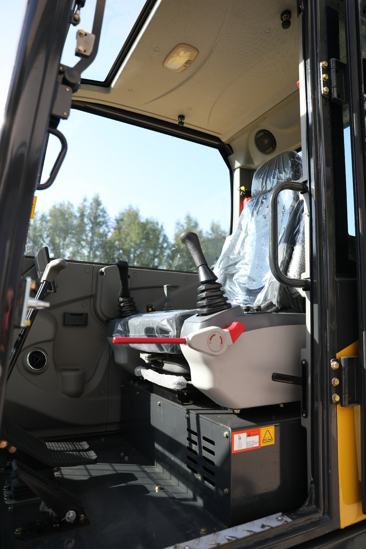
Review sight lines from the actual seat position and confirm the supplied mirrors or other visibility equipment. Do not infer all-around visibility from the shape of the counterweight or from a photograph taken outside the cab.
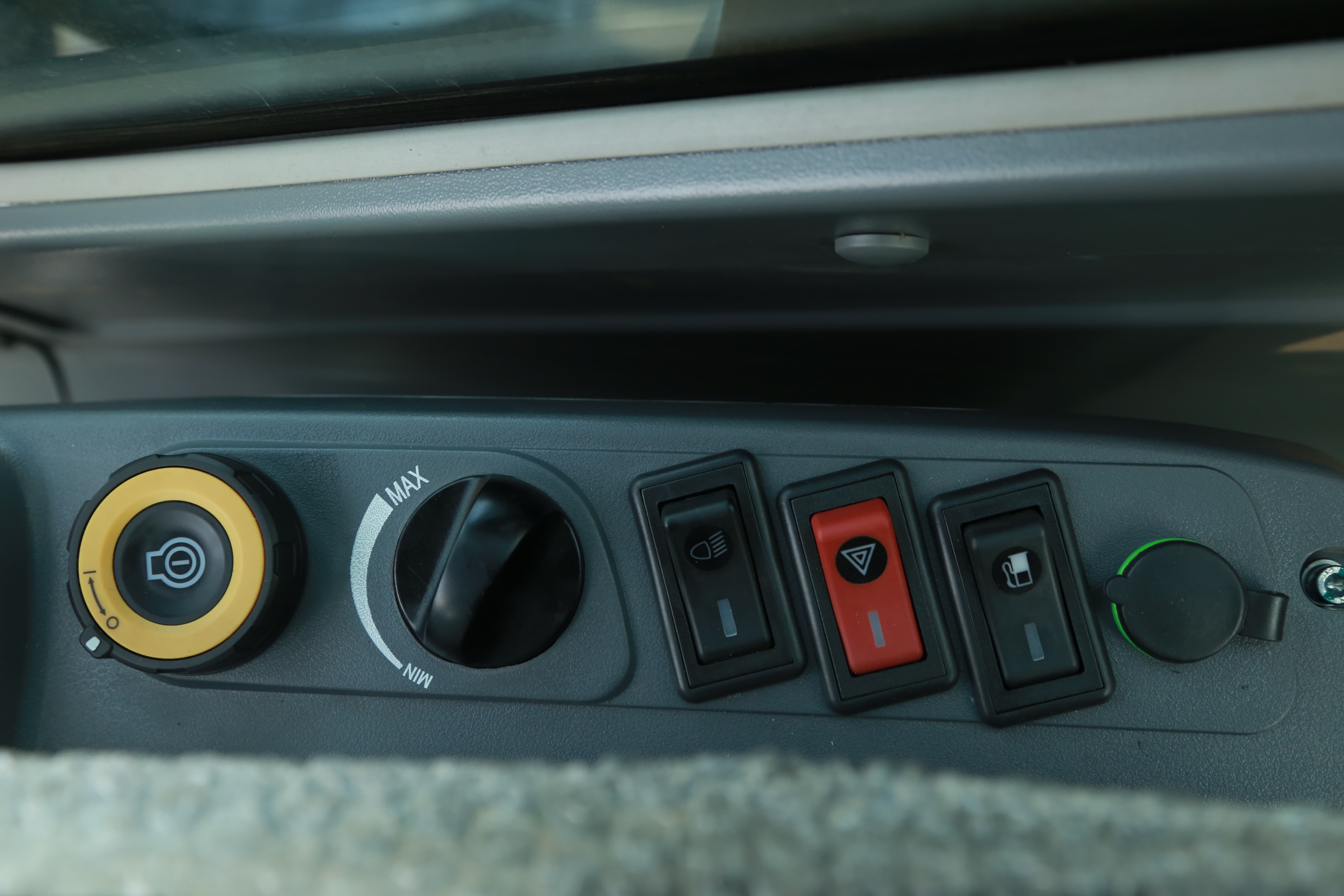
Ask the intended operator to assess access, seating, legroom, and the control arrangement where practical. Tail category alone does not describe these details, and brochure photographs may not show the configuration being quoted.
Request photographs or a demonstration of the routine inspection points and service-panel openings. Record whether the planned maintenance location provides enough room to reach those areas with the machine shut down and secured as instructed.
Keep the model, attachment, track position, and counterweight configuration beside each observation. If one changes, update the comparison before treating the result as evidence for the ordered machine.
Give the supplier enough information to assess the actual restriction. A short, measured brief is more useful than requesting a machine that is simply described as compact.
| Item | Information to obtain | Purchasing question it answers |
|---|---|---|
| Rear dimensions | Tail radius, overhang, and measurement references | How far does the rear actually move? |
| Track configurations | Retracted and extended dimensions where applicable | Which width applies to access and approved work? |
| Complete machine drawing | Top and side views for the proposed configuration | What else may approach an obstacle? |
| Front working range | Boom, arm, attachment, and offset details | Can the machine reach the intended task from the proposed position? |
| Site sketch | Entrance, obstacles, excavation, material routes, and boundaries | Is there a workable arrangement for the complete job? |
| Load chart where needed | Exact configuration and relevant lift positions | Does the model support the intended lifting task? |
| Ordered equipment | Coupler, attachments, counterweight, and other options | Do the drawings match what will be supplied? |
| Operator and service information | Visibility equipment, access details, and maintenance instructions | Can the machine be used and supported as planned? |
Photographs help explain an awkward corner, but include dimensions and identify where they were measured. Show the narrowest opening, the working area beyond it, and the proposed positions of both the machine and receiving equipment.
Mark dimensions that have been measured and those that still need verification. If a model’s rear radius is missing, keep it as an open question rather than estimating it from the product image.
Record the model, drawing revision, supplied attachments, and relevant options in the purchasing documentation. Request updated information if any of those details change before delivery.
For distributors, retain those documents with the specific configuration offered to customers. A generic brochure should not become the only reference for every variation in the product range.
Several purchasing errors come from comparing labels before dimensions. Reviewing these points before the final specification can prevent an unsuitable shortlist.
Zero rear overhang does not mean the machine can be placed against an obstacle without clearance. The complete movement envelope and the project requirements still need to be assessed.
Mini describes a machine category, not a guaranteed rear geometry. Confirm the tail design and dimensions for each model being offered.
A retractable undercarriage can create more than one published width. Identify the permitted configuration for each intended activity rather than carrying the narrowest number into every comparison.
A base machine and a machine with an optional counterweight or attachment are different comparison subjects. Match each specification to its equipment list before drawing a conclusion.
A video can help illustrate movement, but it rarely supplies every reference dimension. Ask for the drawing and configuration details as well, and use any demonstration to answer a defined site question.
It is the movement of the rear upper structure as the excavator rotates above its tracks. Specifications may describe it using a tail radius or rear overhang. The radius starts at the slewing center; overhang describes how far the rear projects beyond the track boundary. Confirm which dimension the supplier has provided.
Usually, no. Zero tail means no rear projection beyond the stated track width in the specified configuration, while short or reduced tail normally retains some projection. Manufacturers may use different category names, so request the actual radius, overhang, and track width instead of comparing the labels alone.
No. The description concerns the rear upper structure. The front of the upper structure, boom, arm, bucket, attachment, or carried load may have a different movement envelope. Ask for the relevant drawings and assess the complete task, including the positions used for digging and material transfer.
That cannot be decided from the tail label. Check access width, height, route bends, the permitted track configuration, front working space, and where material will go. The rear sweep is one part of the assessment. A measured alley plan and the exact machine drawing are needed before selecting a model.
There is no dependable rule covering every model. Stability and rated lifting performance depend on the whole machine, its configuration, and the task. Compare the applicable manufacturer load charts and operating information. A longer-looking counterweight or a similar advertised weight class is not enough to establish the result.
Only if the smaller machine also meets the job requirements. Check the required digging range, approved attachment arrangement, material-handling task, and any lifting requirement. Reduced rear projection may help positioning, but it does not establish that the machine can reach or complete the work from that position.
They can. When the track width changes and the rear radius does not, the amount of rear projection relative to the tracks can change. Ask which track position the published classification describes, and confirm the permitted configuration for each activity in the manufacturer’s instructions before planning the job.
It may change the rear outline, so check the documented dimensions for that option. Do not assume the base machine’s tail radius still applies. Request the revised drawing, operating weight, and relevant load chart together so that the clearance and capacity checks refer to the same ordered configuration.
Review the jobs customers actually need to perform. If restricted rear space repeatedly prevents suitable positioning, a zero or reduced tail model deserves assessment. If sites provide adequate rear room, compare other machine requirements alongside it. A mixed fleet decision should reflect documented demand, support needs, and model suitability.
Send a measured site sketch, photographs, access restrictions, the proposed excavation, and the material-handling layout. Include the intended attachments and any lifting requirements. Ask for the exact model’s rear radius, track configurations, front working range, and relevant instructions so the supplier can assess the proposed arrangement.
Choose a mini excavator tail swing configuration that fits the measured site and supports the complete task. Zero tail swing can be valuable where rear projection restricts positioning; conventional or reduced tail designs may also be suitable when their dimensions fit the available space.
To assess mini excavator tail swing for your next project, share the site layout and working requirements with MAXPOWER. Review the available excavators and request the exact dimensional drawing, attachment information, and applicable load chart before confirming the equipment specification.